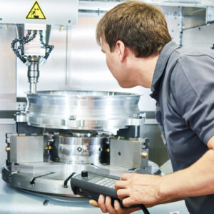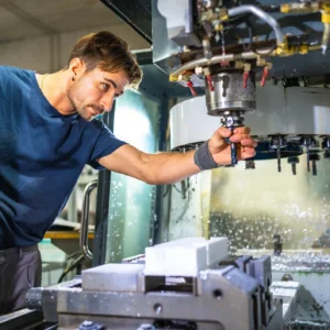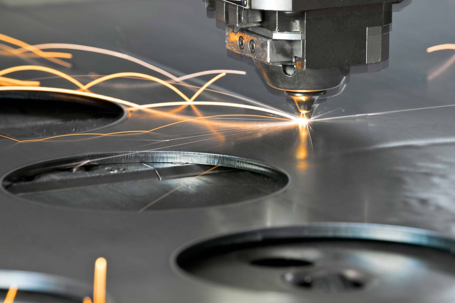
For those working with CNC machinery, the initial impression might be that the equipment is quite complex. While operationally manageable, CNC machines are assemblies of numerous individual CNC mechanical components working together to form a sophisticated machining centre. This intricate design is essential for achieving tight tolerances and producing consistent, high-quality products.
This guide provides a clear explanation of the key CNC mechanical components that constitute a CNC machine, simplifying technical terms and outlining how these parts function collaboratively.
What Is a CNC Machine?
A Computer Numerical Control (CNC) machine is a computer-controlled tool that uses pre-programmed software to direct its movements and operations. This allows for the automated and precise shaping of materials like metal, plastic, and wood. CNC machines are widely used in manufacturing for tasks including milling, turning, drilling, and routing.
Key Components of a CNC Machine
The CNC machine system is a complex network of interconnected components, such as the spindle, MCU and driving system that work together to shape and manipulate the workpiece with high precision.

CNC machines can be broadly categorised into two main systems based on their function: the control system and the machine system.
The control system manages the flow of information, controlling the machine’s inputs, outputs, and actions. This system acts as the interface between the operator and the machine, ensuring accurate part creation.
The machine system, on the other hand, comprises the physical CNC mechanical components that perform the actual shaping of the workpiece.
Control System Components
The control system of a CNC machine is crucial for translating operator instructions into machine actions, enabling precise manufacturing. Key components of the control system include:
Control Panel
The control panel is the primary interface for operators, featuring a display screen and buttons or touch inputs for entering commands and adjusting settings. It allows the operator to communicate directly with the machine, ensuring that the correct parameters are set for accurate execution. The design of the control panel focuses on user-friendliness, ensuring efficient operation and real-time monitoring.
Input Device
The input device is responsible for transferring program data to the CNC machine. Common input devices include:
-
Tape Reader: Reads CNC programs stored on punched paper or magnetic tapes.
-
Magnetic Tape Reader: A more reliable alternative to the tape reader, using magnetic media for storing programs.
-
RS-232-C Communication: A serial communication method used to transfer data between the CNC machine and external devices, allowing for rapid program loading.
Machine Control Unit (MCU)
The Machine Control Unit (MCU) is the “brain” of the CNC machine. It processes inputs from the control panel and input devices, converting them into actionable commands that control the machine’s movements. The MCU also communicates with the feedback system to make real-time adjustments based on the machine’s performance, ensuring precise part production.
Feedback System
The feedback system ensures high accuracy by providing real-time data on the cutting tool’s position and movement. It uses sensors and transducers to measure parameters like speed, acceleration, and position, allowing the machine to make adjustments and maintain optimal accuracy. This continuous monitoring prevents errors and ensures the quality of the final product.
Machine System Components
The machine system comprises the physical components that actually shape the workpiece. These components include tools, positioning mechanisms, and movement systems. Depending on the machine type, either the workpiece or the tools may be stationary while the other moves or both may move in tandem.
Driving System
The driving system consists of motors responsible for the movement of the tools and workpieces. In CNC milling machines, the bed moves horizontally along the X and Y axes, while the tool moves vertically along the Z axis. In CNC lathes, the tool moves parallel to the rotating workpiece.
Key components of the driving system include:
-
Servo Motors: Provide precise control over movement, ensuring smooth and accurate positioning.
-
Ball Screws: Convert rotational motion into linear motion, providing high-efficiency movement.
-
Linear Guides: Allow smooth travel of moving parts, ensuring stability and precision during operation.
Headstock
Located on the left side of a CNC lathe, the headstock houses the main drive, bearings, and gears that rotate the chuck. The headstock controls the rotation of the workpiece and plays a critical role in maintaining torque and speed during machining. It is enclosed for safety but can be accessed for maintenance via inspection panels.
Chuck
The chuck holds and secures the workpiece during machining. In CNC lathes, the chuck rotates the workpiece at high speeds.